Navigation Menu 
[expand all...]
[COLLAPSE ALL...]
|
Expand All
Compress All
CAUTIONARY NOTES:
ALWAYS HANDLE SAMPLES AND MACHINE WITH GLOVES AND/OR TWEEZERS
ALWAYS RAISE THE MICROSCOPE BEFORE LOADING AND UNLOADING SAMPLES
DO NOT TOUCH THE OBJECTIVE LENS
DO NOT SMASH THE OBJECTIVES INTO THE SAMPLE
DO NOT PUSH ON THE ISOLATION PLATFORM
ONLY ROTATE THE OBJECTIVES USING THE ROTATION WHEEL - DO NOT PUSH DIRECTLY ON THE OBJECTIVES TO ROTATE
LEAVE THE TABLE CLEAR OF ALL WAFERS, PAPER, TOOLS, TOWELS, ETC. - ALL MATERIALS LEFT ON THE TABLE WILL BE DISPOSED
TURN OFF THE HEPA FILTER BEFORE YOU LEAVE
SAVE ALL FILES YOU WANT TO KEEP TO AN EXTERNAL USB FLASH DRIVE - ALL FILES STORED LOCALLY ON THE COMPUTER WILL BE DELETED
DO NOT INSTALL UNAPPROVED SOFTWARE ON THE COMPUTER
- General Description
- The Zeta 20 is a fully integrated optical profilometer that provides advanced 3D imaging
and metrology features into one package. It is able to quickly create a 3D composite image of a sample
which can then be easily analysed with their proprietary software.
- Equipment Specifications
- Imaging can be performed with different magnifications depending on the requirements for resolution and field of view. Table 1 provides specifications for standard objectives.
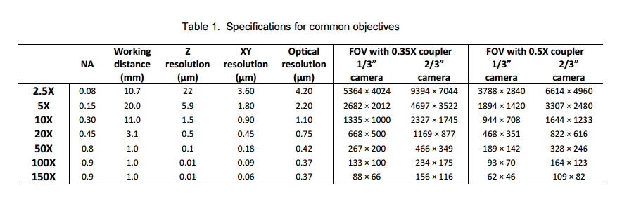 - For more detailed product specifications, click here
- Operating Instructions
Before you start
- Do not place a sample on the platform until the system has been initialized.
- Rotate the turret to place the lowest magnification objective (5X) into the vertical position for measurement.
- Start-up Procedures
- Power up the computer. The Windows password is set at the factory default to "Zeta".
- Power up the Zeta-20 by pressing the round button on the front of the base. It glows blue when the system is powered up.
- Wait 30 seconds to 2 minutes for the computer to recognize the machine on the serial ports.
- Double click on the "Zeta 3D" icon on the desktop to start the Zeta 3D software.
- Log in to the Zeta 3D software in the pop-up window. The user name and password are both set to "a" at the factory. If you would like your own account to edit and save advanced settings, contact the Student Contact.
- Initialization
- The system next performs initialization, which includes the following operations:
- Verify the initialization file settings
- Initialize moving parts including the Z stage and the XY stage
- Press OK to initialize Z Stage and the XY Stage.
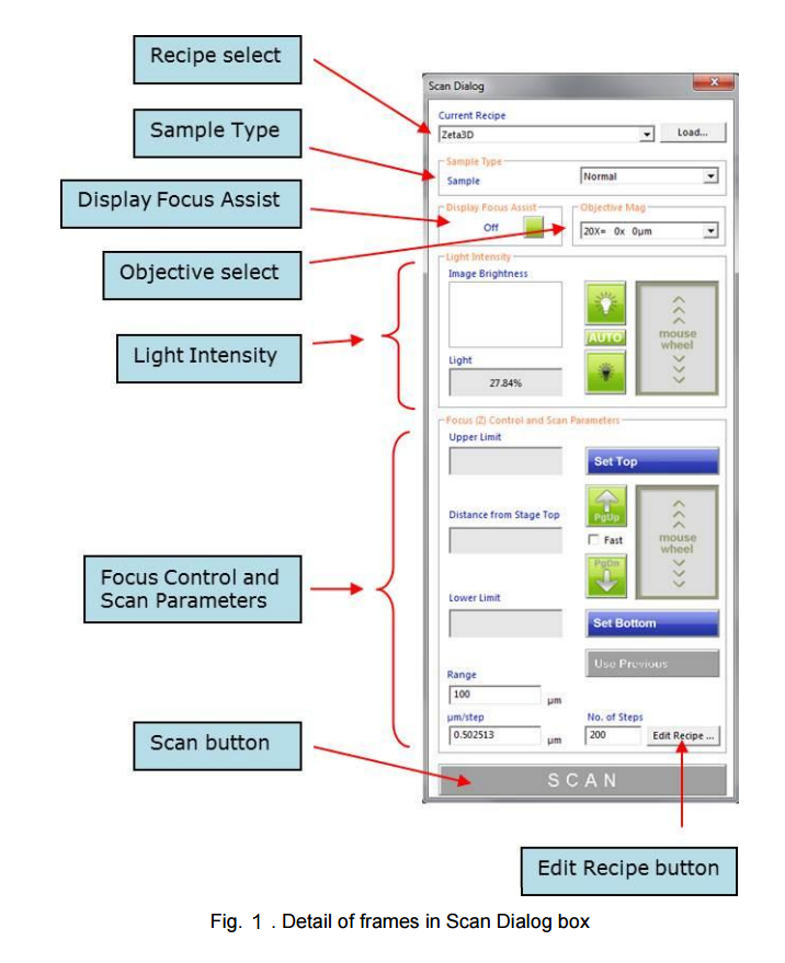
- After initialization is complete, the Zeta 3D software starts up on the Live Video screen. A pop-up window named Scan Dialog also appears.
- If previously created, load a recipe by selecting one from the pull-down list at the top of the Scan Dialog window. Otherwise you can use the default recipe to do your scan.
- Loading the sample
- Place the sample in the center of the stage.
- Use the arrow keys or joystick to position the sample.
- Click the Down button in the Fast Z Motion group located in the Live Image tab. Alternatively, press the keyboard F4 key which is equivalent to the Down button.
- Press the keyboard space bar to move the optical head to the default coarse focus position. The head stops when it reaches a preset safe position.
- Focusing on the sample
- A live video image window is displayed on the screen. A dialog box titled Scan Dialog appears on the right side. However, the image is not usually in focus at first.
- To find the focus position, follow these steps:
- Select the sample type in the first frame of the Scan Dialog box.
- Choose "Normal" for most samples.
- Choose "High" for very reflective surfaces such as metal films.
- Choose "Low" for low reflectivity surfaces such as anti-reflective coatings.
- Verify that the objective magnification in the Scan Dialog matches the physical objective setting, which should be at the lowest magnification level to start. The system should recognizes which objective is in place and changes the drop-down menu selection automatically.
 - NOTE: Be careful not to crash the optical head into the sample. If you cannot see an image in the live video window, look at the objective to make sure that its height above the sample is approximately the same as the expected working distance.
- Find the focus position at low magnification by moving the optical head up and down. Watch the live video image to optimize the image sharpness.
- To move the head slowly, place the cursor inside the focus mouse wheel box and roll the mouse wheel in either direction.
- To move the head at a medium speed while focusing, click on the PgUp or PgDn buttons on the screen, or press the corresponding keys on the keyboard.
- To move the head quickly while loading or unloading samples, use the keyboard F3 key or the Up button in the toolbar to move the head up, and the F4 key or the Down button to move the head down.
- When the head is close to the sample, uncheck the checkbox labeled "Fast" in the Scan Dialog to reduce the Z movement speed in all mouse and button operations.
- To center a feature in the live video window, right click within the window and select the Move to Center Screen option
- Change the illumination level to improve the image.
- Place the cursor inside the mouse wheel box in the Light Intensity frame and move the mouse wheel back and forth.
- To change the settings more quickly, use the Home and End keys instead of the mouse wheel.
- Stop when the green histogram peak is approximately in the center of the histogram box.
- If you have trouble finding the focus on a featureless surface such as a clean silicon wafer or mirror surface, use the Focus Assist feature.
- Decide if higher magnification is required for the measurement. If higher magnification is needed, physically rotate the turret to the new objective.
- Setting the scan range
- To set the scan range using manual focus (recommended):
- Focus on the highest surface of the sample using the mouse wheel for fine focus position control.
- Move the optical head a small amount higher than the highest surface; the image will look a little bit fuzzy.
- Click Set Top to set the top of the scan range. The Upper Limit field displays the Z position.
- Focus on the lowest surface of the sample.
- Move the optical head a small amount lower than the lowest surface.
- Click Set Bottom to set the bottom of the scan range.
- Set the number of steps (in the field labeled No. of Steps). A value of 100 is a good starting point, but the maximum value is limited only by the computer memory. Increasing the number of steps reduces the Z resolution but increases the measurement time.
- To set the scan range using Auto Focus:
- Locate the highest and lowest surfaces of the sample using the mouse wheel for fine focus position control.
- Move the optical head approximately half way between the highest and lowest surfaces.
- Click Set Nominal Focus.
- Set the number of steps, range, or resolution values. The default behavior is to center the Z range at the final auto focus position, so the range should be large enough to accommodate the known feature sizes.
- If necessary, change the way the Z range is set relative to the auto focus position by editing the value of Auto Focus % in the recipe. This is the percentage of the Z range that is scanned above the final auto focus position.
- Taking the scan
- Click on the orange Scan button to initiate the scan.
- During the scan, the head moves from the scan bottom position to the scan top position, taking images at intervals equal to the step size. The Windows rotating circle cursor indicates that the system is busy during the scan and a large red window labeled "Scanning" appears at the top right corner of the screen. You may notice the appearance of the live image change as the head moves.
- Press the Esc key to abort the scan.
- When the scan is complete, the screen changes to display the analysis window.
- Moving and unloading the sample
- Moving to another measurement location
- If you would like to inspect another measurement location without unloading the sample, you can change the sample position using the joystick. If the new location is very close to the old location, the operation is safe. However, if you want to move a large distance, the sample may be too close to the objective if the sample is not flat or if you are using high magnification. Also, you may need to use a lower magnification to find features of interest in the new location.
- To move a short distance (one or two fields of view), use the joystick to change the sample position. Push the top left joystick button to toggle between fast and slow movement.
- To move a large distance, then
- Click the Up button in the Live Image tab or use the F3 key. The optical head moves up and stops at a preset location.
- Change the objective to a lower magnification.
- Move the XY stage to change the sample position.
- Click the Down button or use the F4 key and press the space bar when prompted.
- Focus on the sample following the procedure described previously.
- Unloading the sample
- Click the Up button in the Live Image tab or press the F3 key.
- Rotate the turret to select the 5X objective.
- Move the XY stage to the front right corner of the system.
- If needed, push the sample sideways so that it is not under the objective.
- Remove the sample.
- Working with 3D Images
- See user's manual chapters 5 and 6 for more information on how to manipulate and measure the 3D scanned image
- More Guides
- For more guides on how to use the Zeta-20, see the Quick Guides located under Zeta Instruments/help/Quick Guides on the computer
Comments or suggestions? Submit them here.

|

