Navigation Menu 
[expand all...]
[COLLAPSE ALL...]
|
Expand All
Compress All
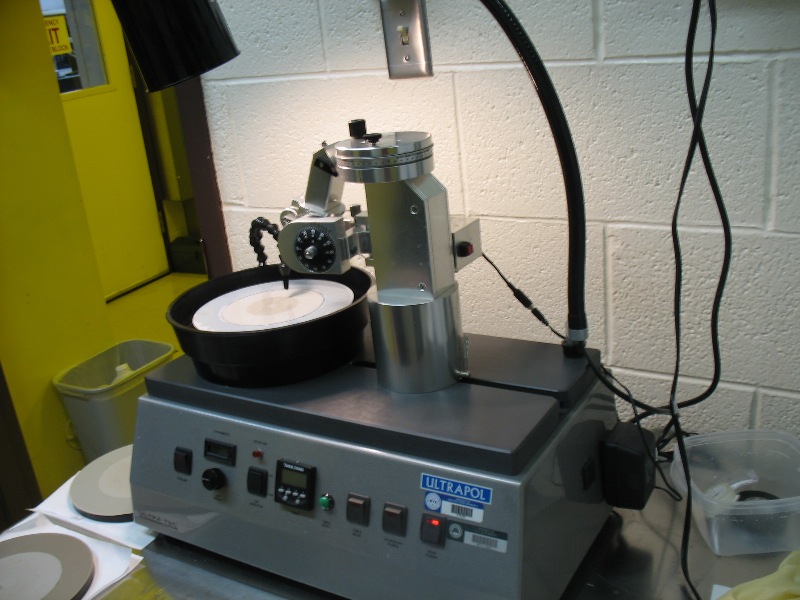
- General Description
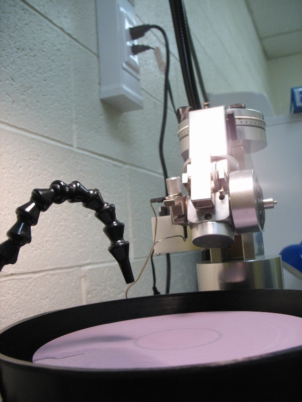
- Ultrapol End & Edge Polisher is used for lapping and polisher. The purpose of this machine is to polisher the edge of the diced wafer sample. The Polisher can polish silicon, Silicon Dioxide(SiO2).
-
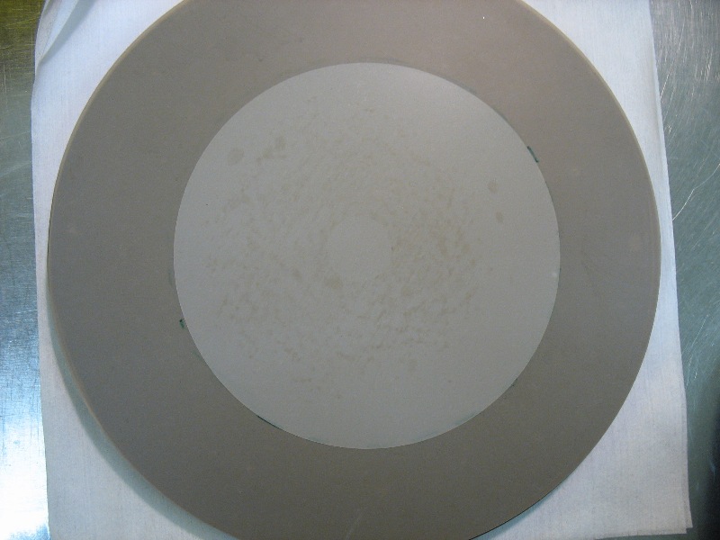
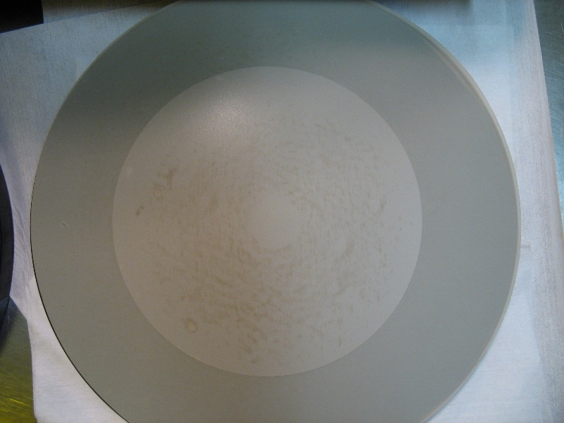
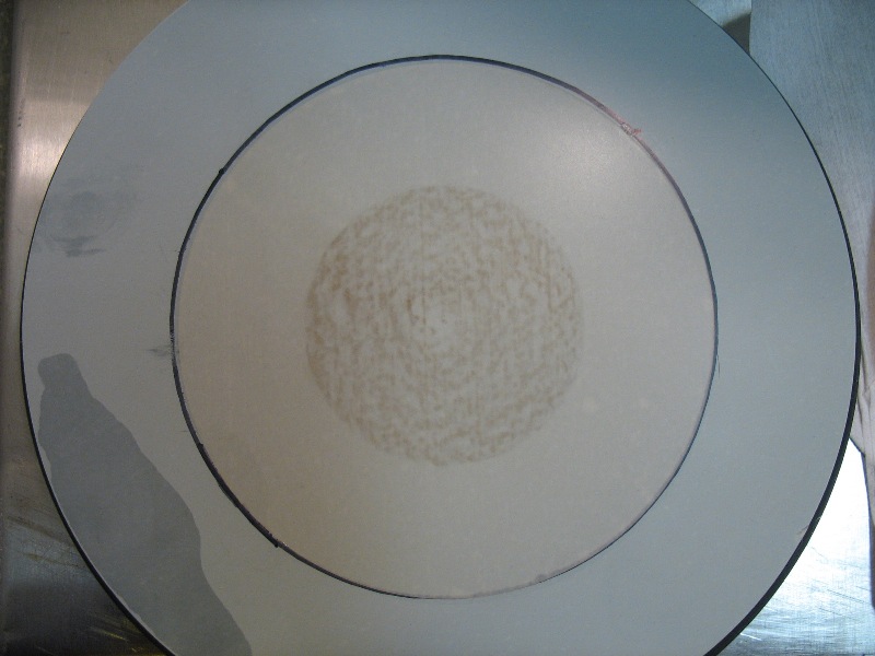
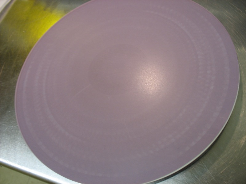
- Different kind of polishing pad:
-
-
-
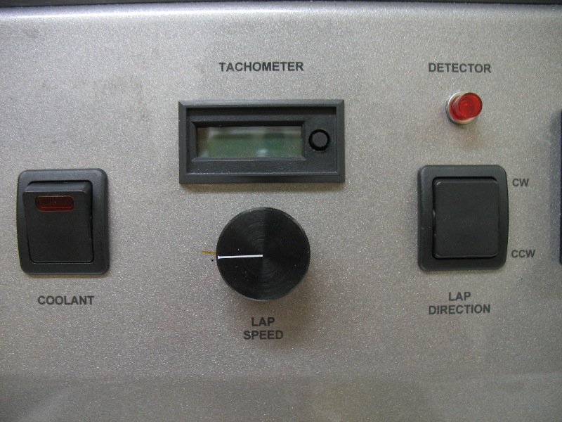
- Polisher Component Definition
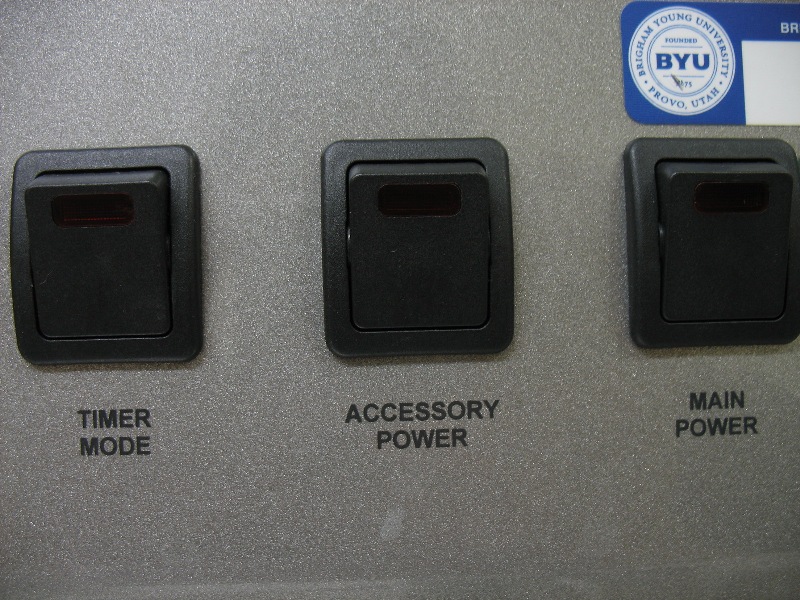
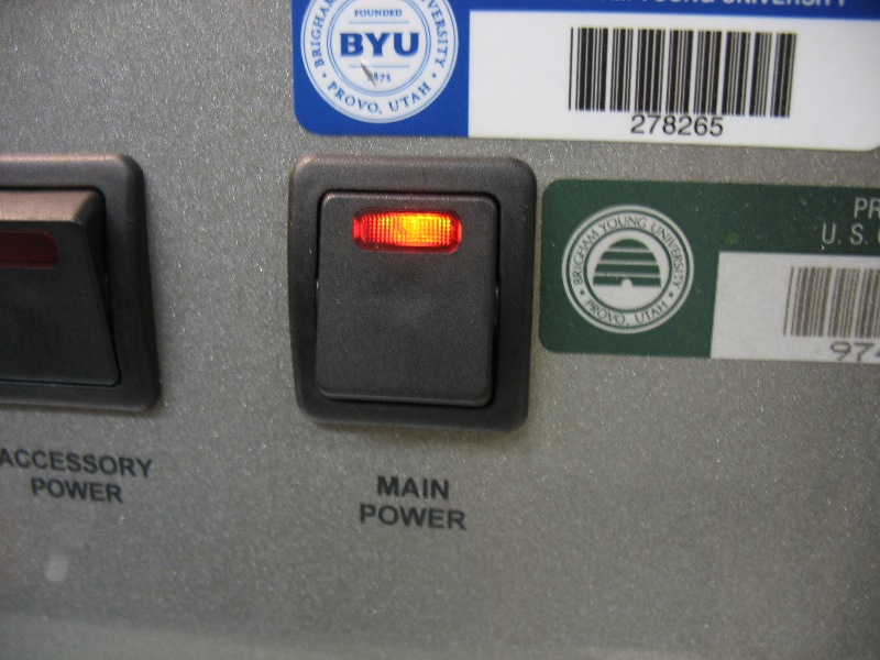
- Main Power Switch
- This switch controls power for all of the functions, with the exception of the rear socket (located on the back panel) which is for the lamp. The Main Power Switch is used to power-up the system after a shutdown period, and should be moved to the OFF position during shutdown. The Main Power Switch is available as an emergency shut-off.
-
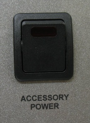
- Accessory Power Switch
- On the right-side panel of the Base, there are two sockets that supply 11OV AC power. The Accessory Power Switch controls these switched. These accessory power outlets are used for accessories (for example, rotating or oscillating devices).
-
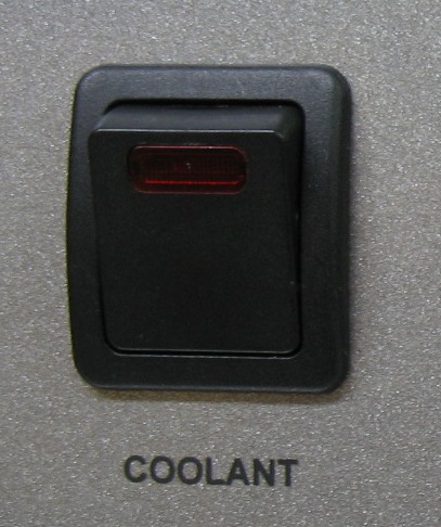
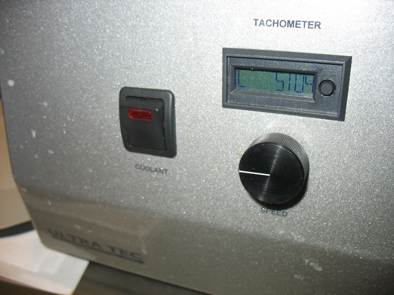
- Coolant Control Switch
- When engaged the Coolant Control Switch will pump water (from an existing source) through he faucet on the top-side of the base. The flow of water can be adjusted with the valve on the faucet.
-
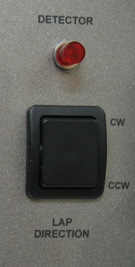
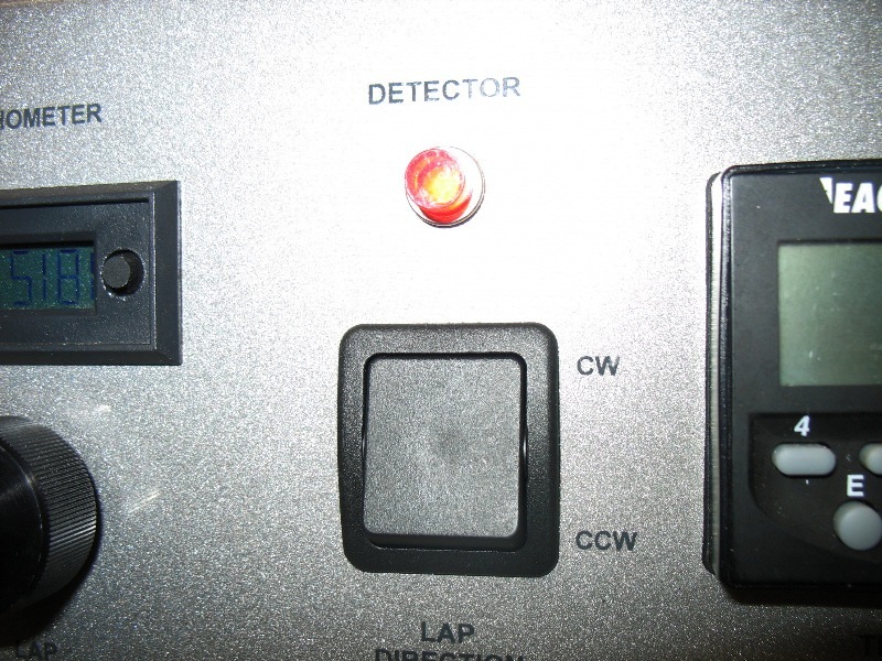
- On/Off/On Directional Switch
- This three-way switch, located to the right of the Timer, has a central OFF position, and two ON positionsClockwise (CW) and Counter-clockwise (CCW)I for selecting direction of the Lap.
-
- Lap Speed selection knob
- This knob is used for selecting speed of the Lap. It can be left in any particular position
-
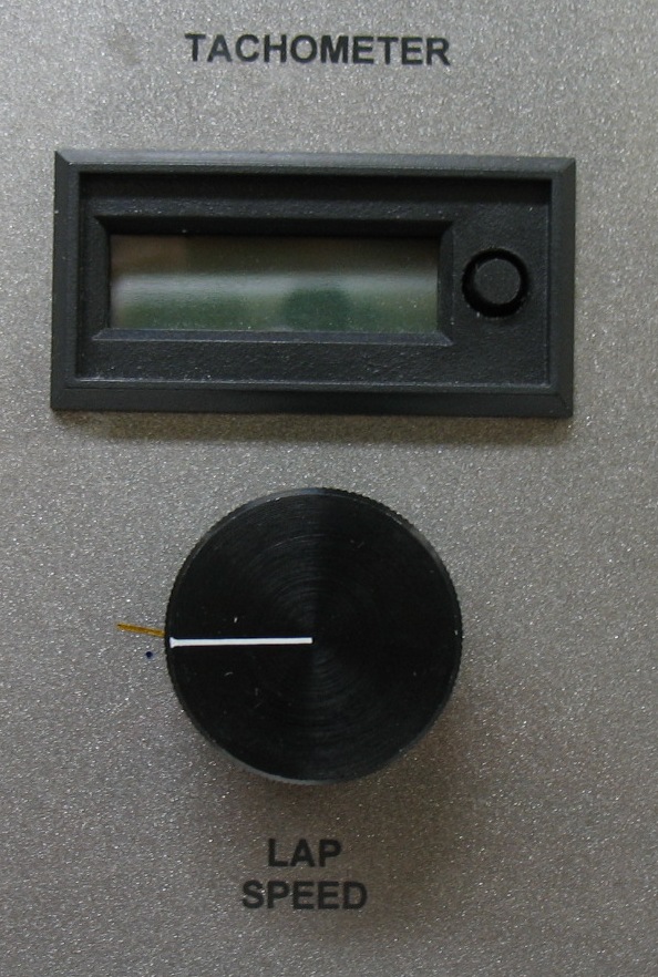
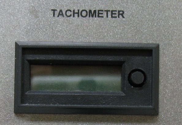
- Tachometer Readout
- The Tachometer Readout reads directly, in RPM, .the maximum speed will be approx. 600 RPM.
-
- Operating Instructions
- Starting Up Procedure
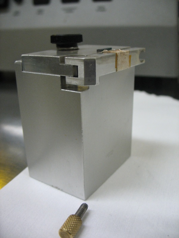
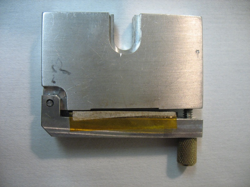
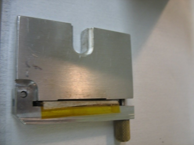
- Prepare the Sample
- Make sure you have the sample ready. Different size of the sample and material will require different polisher pad.
- Put the Sample to the right size of sample holder.
- If your sample is bigger, use the bigger sample holder.
-
-
- Make sure the power cord of the polisher is plugged in.
- Turn on the Polisher by flipping up the Main Power Switch.
-
- The polisher lamp should turn on.
-
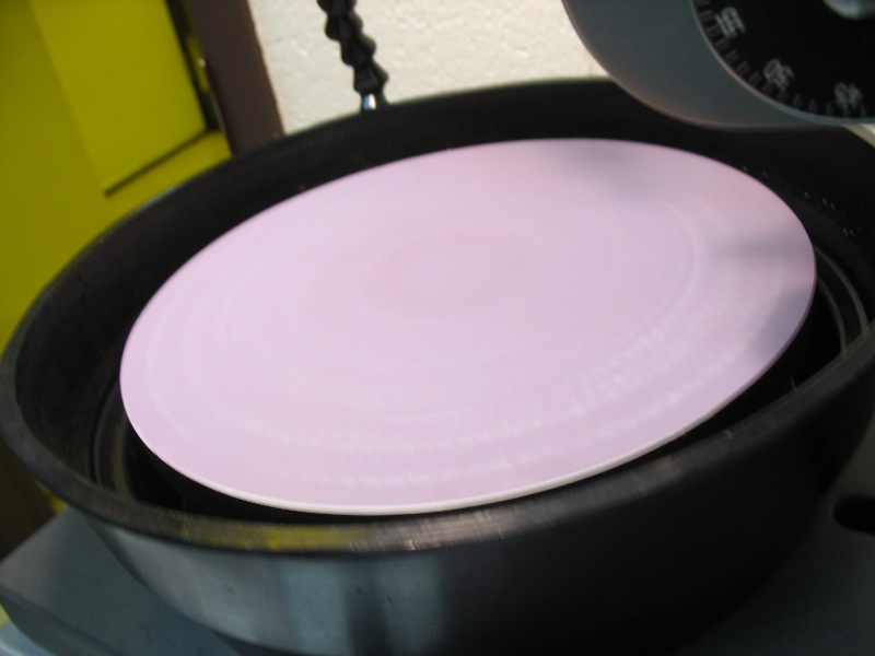
- Install the Polishing Pad on top of the polisher pad holder. Make sure the pad are correctly install and rotatable.
-
-
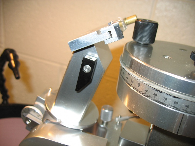
- Install the sample holder on the top of the machanical arm.
-
- Turn the knob to be horizontal in order to put the holder on top of it.
-
- Put the Sample Holder on the top.
-
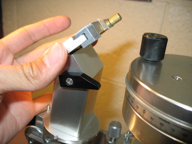
- Turn the knob to lock it back up.
-
- Filp up the COOLANT Switch. DI water should flow down to the polishing pad.
-
-
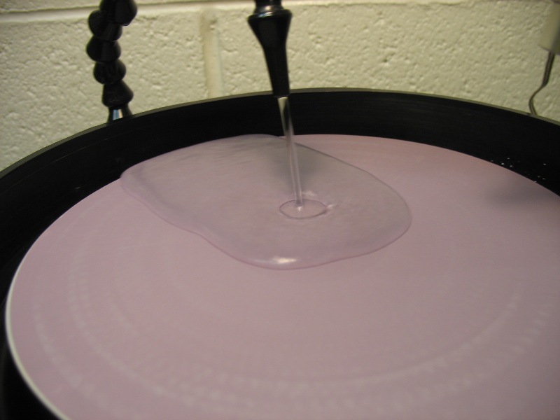
- You can adjust the DI water flow rate by turing the knobs on the back of the polisher.
-
- Flip up the ACCESSORY POWER Switch on the right-side panel of the Base It will turn on the accessories (for example, rotating or oscillating devices).
-
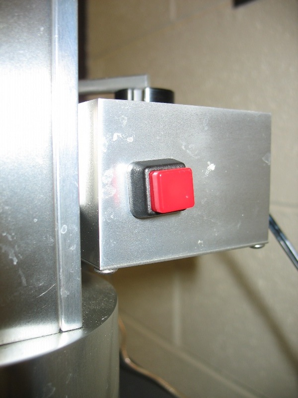
- Press the Red Button to turn on the machanical machanical arm.
-
- Then turn up the LAP SPEED knob and the polishing pad should start rotating. The desired lap speed vary with different application.
-
- The Tachometer above the Lab Speed knob measures the rotation speed of the polishing pad. The maximum speed will be approx. 600 RPM.
-
- Then, choose the lab direction clockwise or counter-clockwise by fliping the LAB DIRECTION swtich. If the switch is in the middle, the polishing pad will not rotate.
-
- Polishing Procedure
- Once everything is set up, drop the machanical arm so the edge of the sample wafer will touch barly touch the polishing pad.
-
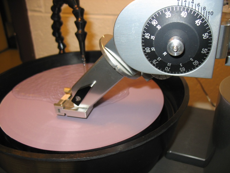
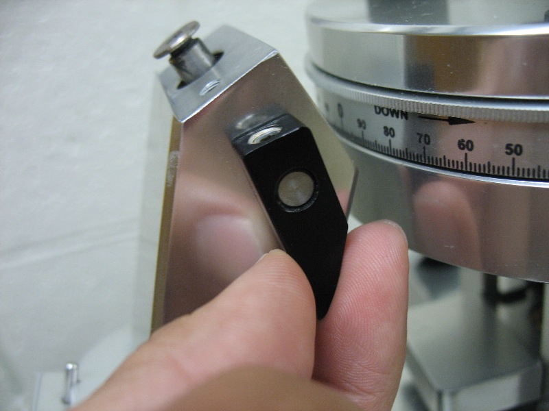
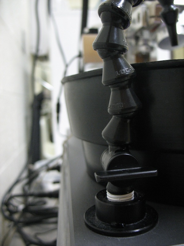
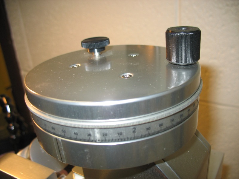
- Adjusting the Micropositioned Head
- The Micropositioned Head provides variable control of the axial angle (0-12°). The angle dial reads the angle between the vertical mast and the spindle that holds the work. The angle is set by use of the Angle Stop and the Angle Fine Adjustment Knob.
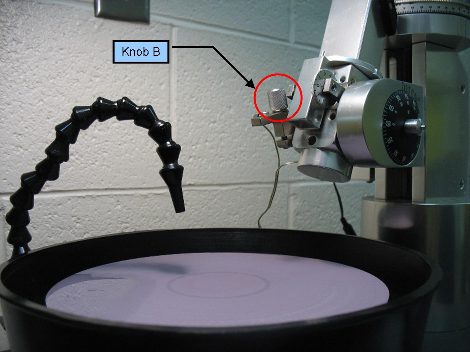
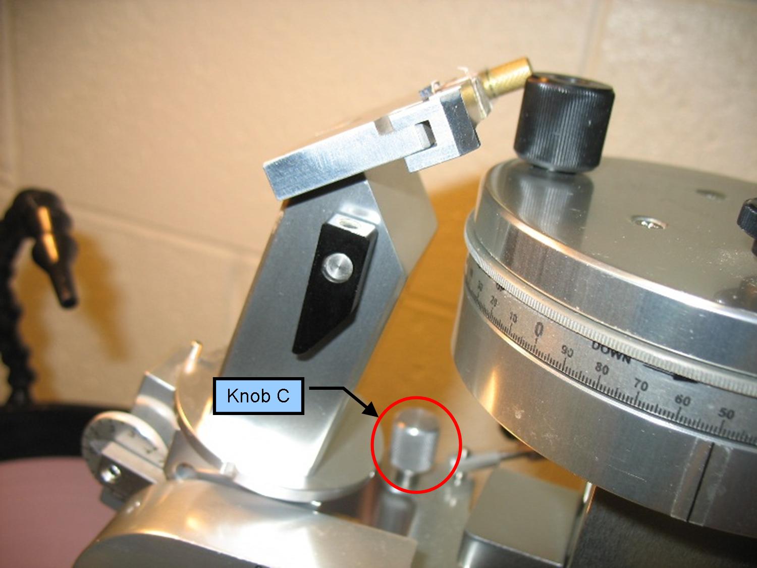
- To set an angle, loosen the knob B until pressure on the spindle allows a slipping movement. Set the angle coarsely and tighten knob B. Knob C is a fine adjustment knob that allows the dialing in of the exact angle. The dial itself has a Vernier type of readout. The dial is spring loaded to remove backlash.
-
-
- Adjust the Height
- The vertical height position is controlled by a leadscrew that is adjusted by turning the vertical knob. The readout is metric, reading like a micrometer.
-
- Once the edge of the sample have contact with the polishing pad, the DETECTOR light above the LAB DIRECTION will be lit up. The polisher is now start polishing.
-
- Adjusting the Oscillator (Optional)
- The oscillator provides a mechanized method of oscillating the sample/workpiece on the rotating lap surface. Used for preparation of the work holder.
- Set the Linkage Bar into place--one hole onto the 'Driver' (rotating) pin on the Oscillator, and a hole at the other end onto the driven pin that extends from the Yoke.
- Adjusting the swing: The Driver Block can be moved, moving the position of the pin relative to the center of rotation, thus controlling the amount of sweep. To set the pin position, loosen the setscrew in the side of the Rotor (it is the upper of two holesthe lower set screw holds the Rotor to its shaft); slide the Pin to its new position at the far side of the rotor, and retig hten the setscrew. The closer to the center of the rotor that the post is, the less is the extent of the swing.
- In general, the sweep of the oscillation should be kept in the front right quad rant of the lap, with a narrow oscillationtypically a centimeter or two1 allowing particles to be washed away. For most operations, wide oscillations are not helpful, and for delicate work oscillations may introduce undesired lateral forces.
- Operation of Oscillator. Press the button to turn the motor on (the power source is also controlled by the Accessory switch on the front panel of the Base-- which is tied into the Timer. Unless a correct depth position has been preset, it is a good idea to let the workpiece hover over the surface as the swing is observed and then gradually lower the vertical setting until contact with the lap occurs.
- Troubleshooting
- If there is any question regarding to the Ultrapol End & Edge Polisher, please email the staff above for more inforamtion.

|

")